|
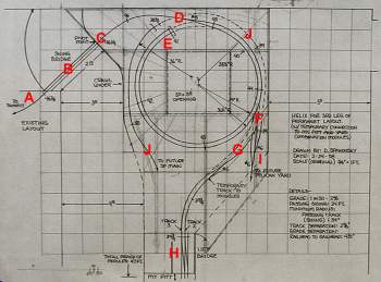
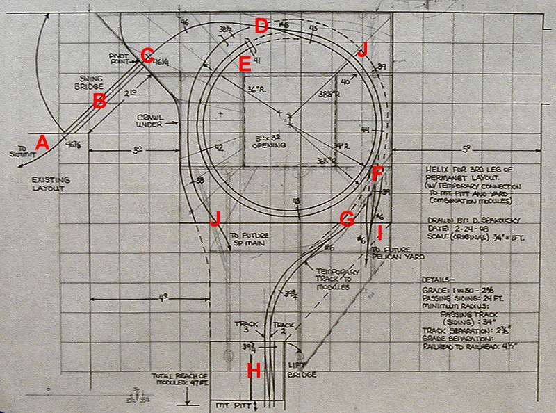
Dave Spakousky drew up a plan for
the
helix and Larry Tuttle developed a framing plan and materials
list.
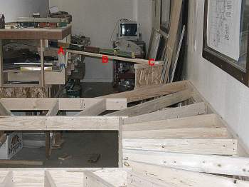
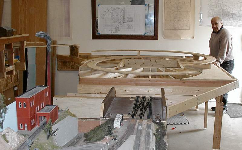
Track on the permanent layout had already been laid to A. A swing bridge will be
built at B connecting to
the helix section at C.
The Keno siding would begin at D,
winding downward and entering a "tunnel" at E. A road at F will conceal the two tracks as
they emerge at G.
Temporary trackage will be laid to the modular lift bridge at H. Eventually, permanent
track will be laid at I
and continue down to connect to the rest of the Klamath Falls
"leg." A continuous run loop will diverge from I to J to allow continuous running
through the P&E, SP and BN yards. Because part of the loop
will be buried in the helix, it is necessary to build it now; it may
connect to the lift bridge at H
to provide staging for BN and/or SP trains.
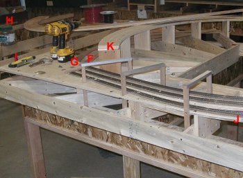
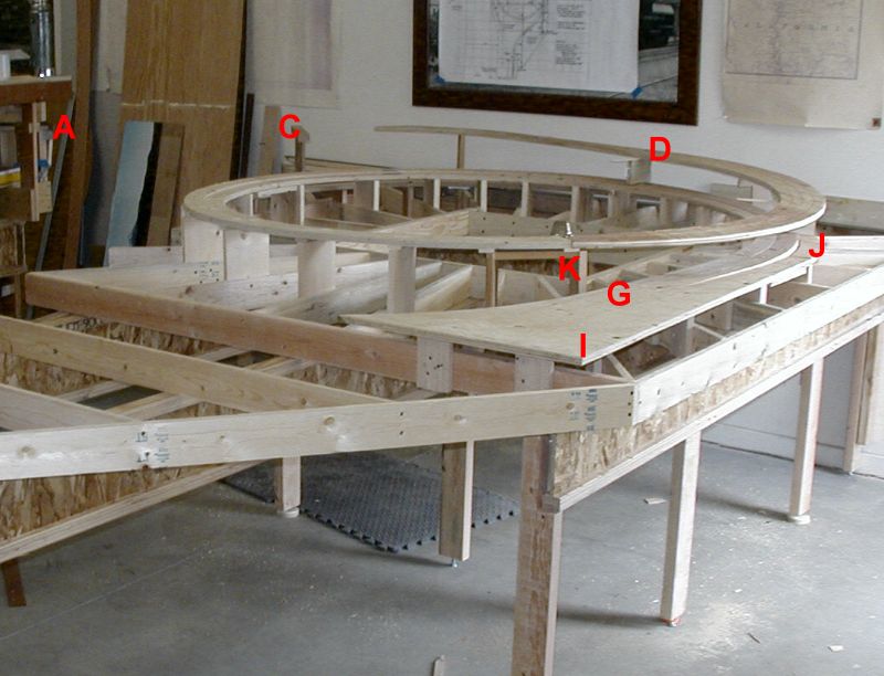
Note the red letters on the plan correspond to similar red letters in
the photos below.
|
|
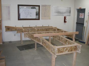
Dave, Larry and
Ed Kleinman spent just over a morning putting together the BCI girders,
and 2
x 4 legs. After five years of working on a layout built with this
type of construction we are convinced that it is superior and VERY
sturdy. It also goes together quickly.
|
|
Initially Larry wanted to
just fasten the helix to the east wall with a 2 x 4 screwed into
studs. However, Dave pointed out that the floor to our clubhouse
as been known to shift up and down and that we might want to allow for
some up and down motion. Larry came up with "truss clips" to
secure the right-most BCI to the wall while allowing vertical
movement.
|
 |
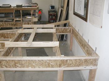
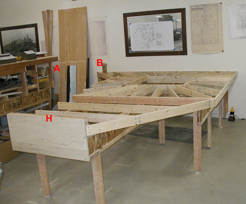
Day Two saw Dave, Ed and
Larry complete the 1 x 4 joist system. The main line leaves the
existing layout at A and
crosses the swing bridge to B.
The temporary lift bridge to the modules will rest on the BCI and
plywood structure at H
|
|
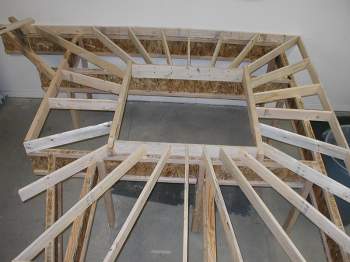
The fan of radial joists is
sort of artsy looking. It will provide ample support for the
helix tracks. With three people working, this part went
fast. Lengths were marked ot each joist by holding it in place
(no measuring!) and at the same time taking the angle with a sliding
T-bevel. Then the chop saw was set to the angle and two cuts made
on the lines. Drywall screws hold everything together. The
trick with screws is to pre drill/countersink each hole. 1 x 4's
can then be "toe screwed" into BCI's and other members at up to a
30º angle to the 1 x 4.
|
|
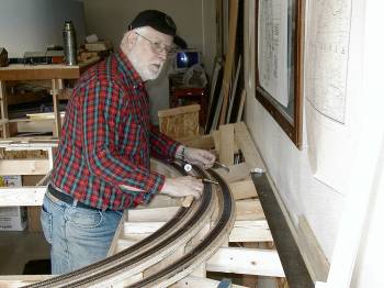
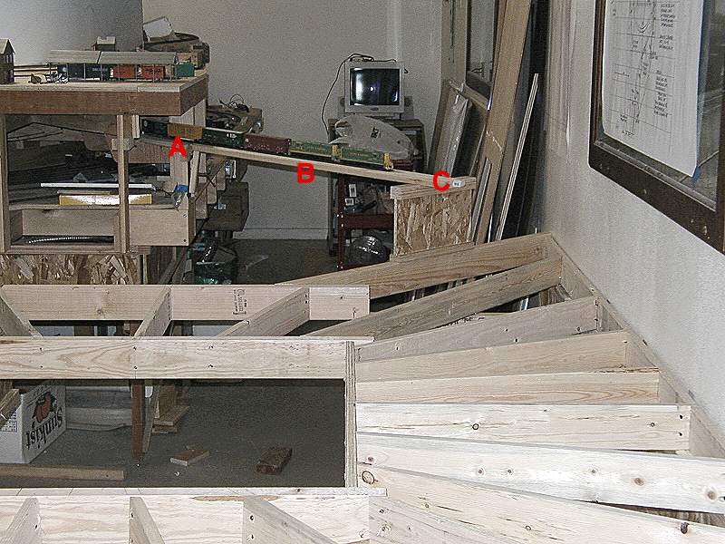
After a couple of very
productive days, we took a minute to stage the "First Train to
Nowhere". It's coming off the permanent layout at A, over bridge site, B and onto the helix benchwork
at C.
|
|
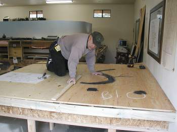
Day Three began as we spread
out two sheets of 3/4" plywood and Dave laid out the helix
curves.
|
|
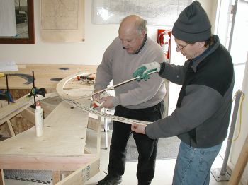
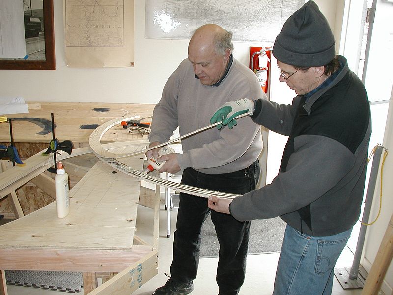
This
picture begs the "Caption This" title.
Spreading mayo on a roadbed sandwich?
Actually, Dave and Ed are re-gluing a "blow" or section of plywood
which had delaminated. While it's kind of a nuisance, the plywood
was donated and most of it is in good condition. An hour with
clamps and this piece sub-roadbed will be as strong as any other.
|

|
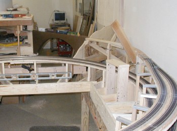
A morning of drawing and
sawing (and gluing) and the sub-roadbed was ready to be installed on
risers.
We also moved Mt. Pitt (foreground) to its new location and clamped the
lift bridge (brown contraption) in place.
|
|
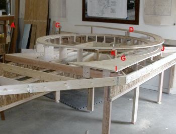
By the end of Day Four, the
sub-roadbed for the lower level of the helix had been permanently
anchored on risers. The plywood from K to D was just laid in place for
this picture since track needed to be laid on the lower level
first. There was just a little more work to this than first meets
the eye. Our standards for layout construction require
super-elevation on main line curves. We also want the main
line elevated slightly (~1/4") above secondary trackage.
While the inside passing track was simply screwed to risers, the main
line required shims to raise and super-elevate. A little more
work, but a most dramatic effect when complete.
|
|
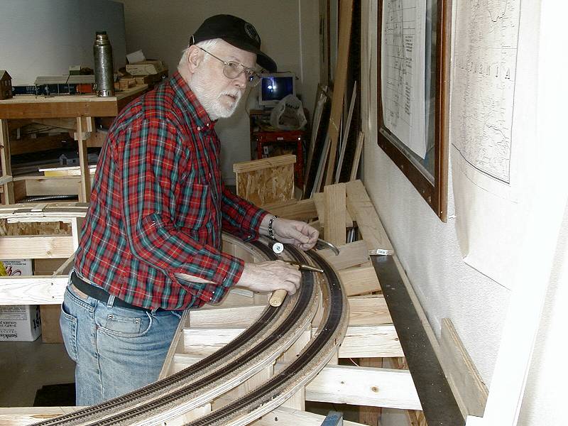
Road Master E. Don got right
to work laying the track for the first level. He wanted to stay
ahead of the sub-roadbed going in for the second level.
|
|
Next was the support system
for the second level. Larry insisted that building the second
level directly over the first could be done...easily and
sturdily. He almost wished he hadn't said that until he came up
with inverted 3/4" x 1/2" extruded aluminum channel supported by 3/4" x
3/4" wood "cube". It kind of looks like over-sized supports for
catenary. The sub-roadbed was drilled and screwed through
the aluminum (with shims for the main line) and made for a very sturdy
helix structure.
|

|
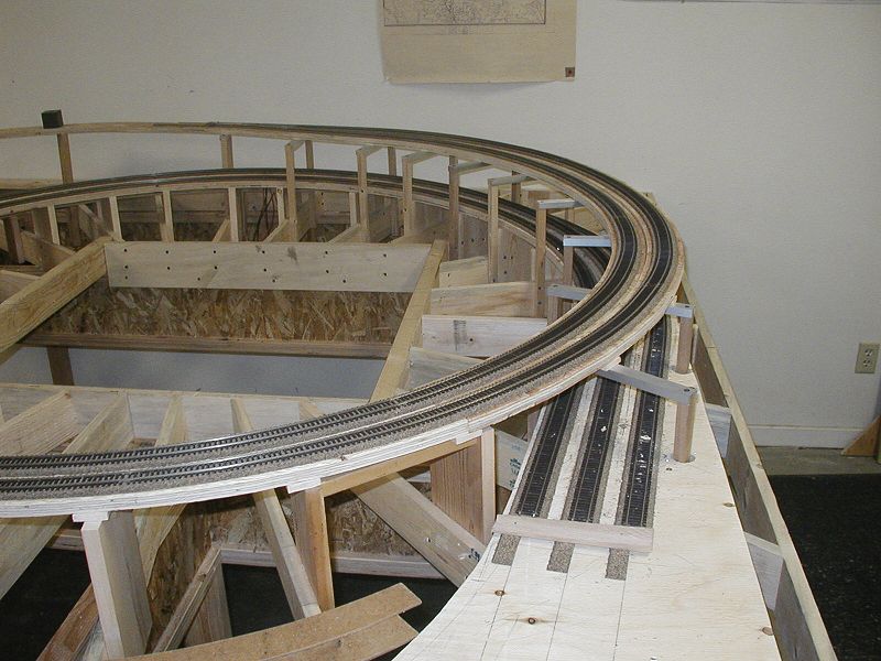
The ascending main line and siding stacked neatly over the lower level tracks.
(Ed. note: In the three years the helix has been in use, this construction method has proven very sturdy and relaible with no adjusments needed in the track support system.)
|
 |
With the bulk of the helix track laid, attention turned to getting the main line across the aisle and connected with the rest of the layout. Several options were considered including a fixed duck-under (which was immediately nixed!), a lift-out section (also nixed) and a swing-away bridge. The swing-away bridge would be the choice IF it could be built sturdy enough and made to operate reliably. |
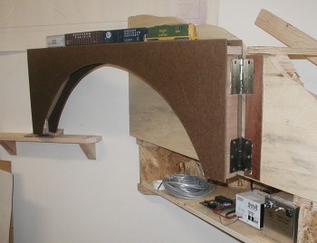 |
Larry fabricated the roadbed and ends of the bridge out of 2 1/2 x 3/4" material and braced it with two diagonals. Then, he cut 3/16" Masonite into a pair of arched bridge sides and glued and pinned them in place. The resulting structure is very rigid. A pair of 3 1/2" butt hinges hold the bridge securely to the benchwork while allowing it to swing out of the way for people. DCC bus wires were soldered to each hinge half and electrically conductive grease lubricated the hinges. This eliminated the need for any loose wires attached to the bridge. A roller catch was drilled up into the bottom of the other end of the bridge and lodges into a receiver plate mounted on a little shelf on the far wall. Not shown are two micro-switches, one on each side, which interrupt track current for four feet or more in each direction when the bridge is open. |
 |
A pop-up is built in the middle of the helix and basic land forms are developed. Then, after a trip to Klamath County and a hike on an old Weyerhaeuser grade, a spectacular scene takes shape. |


